
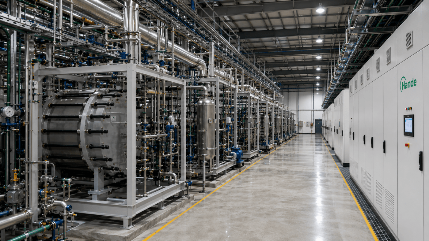
Most feasibility studies for wind- and solar-coupled hydrogen projects lead with the numbers everyone expects: rated production capacity, specific energy consumption, capital cost per megawatt. Far fewer lead with the number that, in practice, does more to determine whether the project actually works: the electrolyzer’s minimum stable load, or turndown ratio.
That gap matters because renewable power is not a steady input. It is a bottleneck hiding in plain sight — and it shows up not in the datasheet’s headline figures, but in how the stack behaves during the hours the wind drops or a cloud bank rolls through.
The core engineering problem: renewables don’t hold still
Solar and wind resources are inherently variable, and the variability is often faster and deeper than intuition suggests. Passing cloud cover can cut a solar array’s output by as much as 80% in under a minute, and both overcast and rainy conditions routinely suppress daily output by 40–45% relative to clear-sky expectations. Wind resource adds its own layer of short-term turbulence on top of slower seasonal swings.
For a hydrogen plant tied directly to a wind or solar asset — particularly off-grid or lightly grid-connected configurations common in large renewable energy bases — this creates two engineering headaches that conventional EPC designs, built around steady, near-rated operation, were never meant to solve:
- Narrow load bands trigger unplanned shutdowns. Conventional alkaline electrolyzers typically hold their safe operating window only within roughly 20–30% of rated capacity, with commercial systems commonly cited at a practical floor near 30–40%. Below that, hydrogen crossover into the oxygen stream approaches the safety interlock threshold and the unit trips offline — turning a modest dip in renewable output into a full stack shutdown.
- Frequent cycling accelerates equipment wear. Repeated start-stop cycling stresses electrodes and diaphragms; industry commentary on legacy alkaline designs puts typical electrode service life at only a few thousand start-stop cycles before performance degrades — a real cost driver once daily cycling becomes routine rather than exceptional.
The result is a familiar and expensive workaround: oversized battery or hydrogen buffer storage sized to carry the plant through every low-output hour, rather than the electrolyzer itself accommodating the fluctuation. That storage buys reliability, but it also consumes a large share of project capital that could otherwise go toward electrolyzer capacity or renewable generation.
What the technology actually supports: ALK vs. PEM
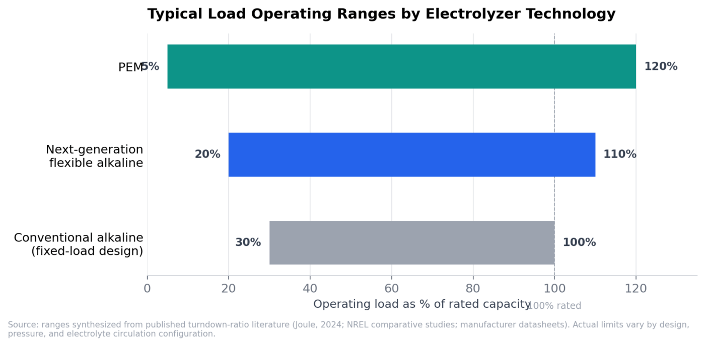
The three broad categories of electrolyzer deployed at scale today differ substantially in how far their operating range extends below rated capacity — and that difference is the single largest lever available to reduce dependence on buffer storage.
- Conventional alkaline (fixed-load design): The workhorse of large-scale green hydrogen to date, valued for low materials cost and long operating history, but engineered around continuous near-rated operation. Published turndown figures place the practical floor around 20–30% of rated load, with many commercial units effectively requiring 30–40% to stay within safe gas-purity limits.
- Next-generation flexible alkaline: A newer generation of alkaline stacks purpose-engineered for renewable coupling — using wider electrode spacing, segmented current paths, and more responsive control systems — has pushed the practical minimum down toward 20% of rated load, with some designs supporting short-term overload above 100%. This is increasingly the technology of choice for utility-scale renewable hydrogen bases, though it is still a relatively young commercial category compared to conventional alkaline.
- PEM: Offers the widest operating window and by far the fastest dynamic response. Independent testing, including a National Renewable Energy Laboratory comparison of alkaline and PEM systems, found both technologies could adjust current from 0% to 100% within half a second at the electrical level, with PEM systems commonly quoted with turndown as low as 5–10% of rated capacity. That responsiveness makes PEM attractive for distributed or peak-shaving hydrogen applications, though higher stack costs still limit its use at the largest, centralized scale.
The practical implication for EPC design is straightforward: the wider an electrolyzer’s usable load band, the smaller the buffer storage system has to be to keep the plant running through renewable troughs — and the fewer trip-and-restart cycles the equipment sees over its lifetime.
Dynamic response matters as much as the static range
A wide load band on a datasheet is only half the story. What happens during the transition between load points — switching speed, gas-purity stability, and tolerance for repeated, unscheduled load changes — is what actually determines whether an automation and control strategy built around that electrolyzer will hold up in the field.
A single solar array can see dozens of meaningful power swings in one day; wind resource is in near-continuous flux. Electrolyzers with sluggish load-following and low fault tolerance respond to that environment with hydrogen purity excursions, thermal and pressure imbalances, and irregular electrolyte circulation — all of which show up later as maintenance events.
Newer flexible-load alkaline designs address this with re-engineered flow paths, tighter thermal control, and faster electrical switching logic, with full-range load transitions (100% down to 20% load and back) achievable in on the order of tens of seconds rather than minutes, while holding hydrogen purity at the 99.999% level required for industrial use even under continuous load-following operation. For EPC teams, that shifts the default design pattern away from “fixed-load electrolysis plus large buffer storage” and toward “flexible electrolysis plus a right-sized buffer” — a meaningfully simpler control architecture with fewer failure modes.
The economics: how turndown ratio reshapes storage sizing
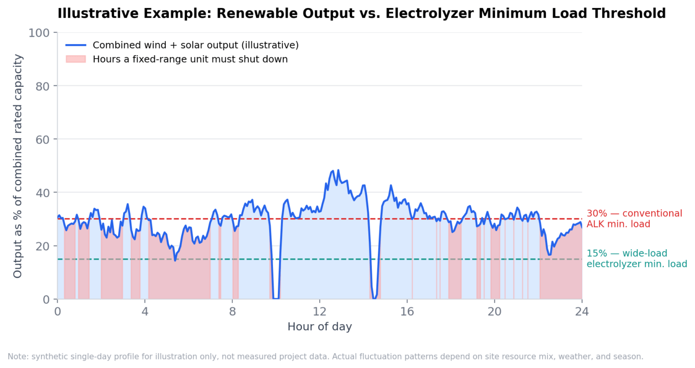
Because buffer storage exists specifically to carry the plant through the hours an electrolyzer cannot operate, the minimum load threshold is effectively a direct input into the storage sizing calculation — not a secondary consideration.
The chart above is a simplified illustration, not measured project data, but the underlying relationship holds across real projects: every percentage point the minimum stable load can be pushed down converts hours that would otherwise force a shutdown into hours of continued, if reduced, production. Independent modeling of electrolyzer flexibility has similarly shown that deliberately oversizing electrolyzer capacity relative to the renewable resource — effectively giving the system more room to operate within its band — measurably reduces the ramping burden that would otherwise fall on storage and grid balancing.
In practical EPC terms, teams that have pushed minimum stable load down toward the 15–20% range report being able to reduce buffer storage capacity on the order of 15–20% relative to a conventional 30%-floor design, since the electrolyzer itself absorbs most of the day-to-day fluctuation and storage is reserved for genuine extremes — near-zero wind and irradiance simultaneously, rather than routine dips.
That has a compounding effect on project economics:
- Less battery or hydrogen-storage capital.
- A smaller footprint for the associated civil works, fire protection, and switchgear.
- In many cases, the ability to right-size the renewable generation array itself rather than over-building wind and solar capacity purely to compensate for electrolyzer inflexibility.
A case in practice: cold-climate wind-solar-to-chemicals integration
A recent large-scale EPC project in China’s northeast — a region with winter lows near -30°C, which adds thermal management to the list of engineering constraints — offers a useful illustration of how these principles play out at scale, without needing to attribute the figures to a specific developer.
The project pairs an 800 MW wind-and-solar generation base (roughly 750 MW wind, 50 MW solar) with a 67,200 Nm³/h flexible electrolysis matrix built from 64 large-format alkaline units, downstream synthesis of roughly 200,000 tonnes per year of green ammonia and 20,000 tonnes per year of green methanol, and a dual buffering approach combining 50 MW/2h electrochemical storage with 15 large gaseous hydrogen storage vessels. Total EPC investment across the first phase came to roughly US$960 million (approximately RMB 6.95 billion).
A few design choices stand out as directly attributable to wide-load electrolyzer selection:
- Load range and ramp rate: The electrolyzer array is specified for 20–100% load operation with a ramp rate of 3–5% of rated power per second, and is built in modular clusters of four units sharing balance-of-plant equipment — so a local power dip trims output from one cluster rather than forcing a full-plant trip.
- Reported durability gains: The developer’s technical documentation attributes a 40%-plus improvement in diaphragm/membrane service life to the reduced start-stop frequency the wider load band enables, versus a conventional fixed-range design.
- Storage right-sizing: The dual hydrogen-sphere and battery buffering strategy was reportedly sized 15–22% smaller than an equivalent conventional-electrolyzer design would have required, based on the electrolyzer’s ability to track renewable output directly rather than shutting down below a 30% floor.
- Cold-climate integration: Because the region’s winters push well below freezing, the EPC scope also had to fold in insulated housings, pre-heating, and heat-traced piping to keep stack operating temperature in the 25–85°C range — a reminder that wide-load capability and thermal management are usually solved together in extreme-climate projects, not separately.
- System-level coordination: An integrated digital-twin control platform (combining energy management, safety instrumentation, and distributed control) was used to coordinate renewable forecasting, storage dispatch, and electrolyzer load-following in real time across two sites roughly 70 km apart — generation and downstream chemical synthesis — which the flexible-load electrolyzer design made practical without requiring the synthesis plant to run at a constant, decoupled load.
The broader takeaway is not the specific numbers — every site’s resource profile, grid conditions, and downstream product slate will differ — but the pattern: once the electrolyzer’s operating range stops being the binding constraint, storage, land footprint, and control complexity can all be optimized around it rather than the other way around.
What this means for project developers and EPCs
A few practical conclusions follow for teams evaluating electrolyzer technology for renewable-coupled projects:
- For large, centralized green hydrogen bases, next-generation flexible alkaline electrolyzers (roughly 20–110% load range) currently offer the best balance of low unit cost and renewable-following capability for long-duration, grid-scale deployment.
- For distributed or peak-shaving applications with the most severe short-term volatility, PEM’s sub-10% turndown and sub-second response remain the better fit, cost considerations permitting.
- Storage sizing should be derived from the electrolyzer’s minimum stable load, not defaulted to a one-size-fits-all buffer — a design step that is easy to skip in early-stage feasibility work but expensive to correct later.
- Control strategy should be built around the electrolyzer’s actual dynamic response profile, using tiered or predictive load-following logic to minimize full start-stop cycles rather than reacting to them after the fact.
Static, rated-capacity thinking made sense when electrolyzers ran on stable grid power. It does not transfer cleanly to a wind- or solar-coupled plant, where the minimum stable load — not the maximum — is usually what decides whether the storage system, the control architecture, and ultimately the project’s return on investment come together the way the feasibility study assumed.
This article was prepared by the electrolyzer engineering team at Hande Hydrogen, drawing on published technical literature and field experience integrating alkaline and PEM electrolyzer systems into wind- and solar-coupled EPC projects.
Sources referenced: Joule (2024), “Alkaline electrolyzers: Powering industries and overcoming fundamental challenges”; NREL comparative alkaline/PEM dynamic-response testing as cited in Journal of Power Sources (2024); Communications Engineering (2023), “Efficiency and consistency enhancement for alkaline electrolyzers driven by renewable energy sources”; published PEM turndown and ramp-rate literature; U.S. DOE/OSTI modeling of electrolyzer flexibility and ramping mitigation.